This is the second part of eight in this series. Visit the main article here.
PART 2: BUILDING the WINCH-IT-UP MAST SUPPORT
The 4x4x12′ will be cut based on the 8 foot length of the top mast section. From above ground all support options will have the same 4x4x10′ main section plus the 8″ add-on at the top.
Each mast has two 4″ Standoff Brackets, a strap winch and some other small pieces. You will also need up to 5 feet of a 1×4″ pressure treated (PT) board. Important Note: The two 4″ Standoff Brackets need to be rated for at least a 2-1/2″ mast size and purchase the type with the removable front strap. See figures 10 and 15.
The strap winch can be locally procured and comes standard with a 20 foot strap. With an 8′ top section, the 20′ standard strap will work just fine.
The support can be configured in different ways to meet your needs.
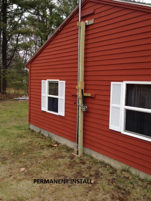
Option 1. Wall Mounted/Attached.
Option 2. The Stand Alone/Portable. This option will require having three (or 4) guy ropes near the top of the 4x4x10′ for stability.


OPTION 1: Wall Mount/Attached
This method mounts your mast directly to a wall. Look for at least one stud to connect to your mounting mechanism. See Figures 12 & 13.
Step 1. For this option cut a 10 foot length, and two 8″ pieces. You will also need two 12″ pieces and two 15″ pieces of 1×4″ pressure treated board. Two 12″ pieces will hold the standoff brackets and the two 15″ pieces will hold the top 8″ section to be added to the main 4x4x10′ section. You will also need some sheet metal scraps to overlap the top of the 10 footer, about 12 inches of it. See Figure 14 for construction layout.

Step 2. Attach a 12″, 1×4 crosspiece to the main 4×4 up about 6-1/2 feet centered with two 5/16″ Lag Bolts. If you have the Standoffs on hand, you can drill and mount one standoff centered on this crosspiece. I use 5/16″ x 1-1/2″ bolts for this.
Step 3. Move up to the top of the 4×4. Hopefully, you have a fairly straight and not badly warped length. Attach two 1x4x15″ PT pieces vertically to the sides of the 4×4 as follows. See Figs. 14 & 15 for orientation direction. Overlap 6″ onto the main 4×4 and attach with three 5/16″ lag bolts set in a triangular pattern. Repeat the process for both sides.
Step 4. Now take your 12″ sheet metal piece and equally spread it over the top of the main 4×4. Attach on one side with roofing nails, then pull it tight over the top to the other side and attach. Make sure the sheet metal spans the Total Width of the 4×4 top. I had to overlap two pieces of sheet metal to cover the total width. Make sure the sheet metal fully covers the opening including any spaces between boards. This sheet metal will reduce the friction from the strap as it goes across while raising.
Step 5. Take an 8″ piece of 4×4 and attach it to the two side pieces of the 1x4x15s as follows. Leave a one (1) inch opening above the main 4×4′. That leaves 8″ to mate evenly with the top of the 1x4x15″ pieces. Drill and attach with three 5/16″ lag bolts in a triangular pattern. Repeat the process on the other side. The 1″ opening allows for the winch’s strap to easily pass through. See Figure 14.
Step 6. With the other 1x4x12″ piece, you can mount it in the center of the 8″, 4×4 piece, but do not mount the standoff to it yet. It is placed about 1/2″ above the bottom of the 4x4x8″. The standoff will be mounted later when you square your mast vertically.
Step 7. Mounting the Strap winch. Mine has three mounting holes on it. I used 5/16x 1-1/2″ lag bolts for this. I mounted mine up about 5-1/2′ from the ground. Try to align the two top holes on a level straight line to help keep the winch mounted as level as possible. See Figure 16 for its’ orientation on the 4×4. It mounts on the backside of the standoff brackets. Because the antenna, rotator and mast itself have substantial vertical dead weight, it may be difficult for some to easily crank the winch. What I did was add a length of steel bar that I found to the crank handle to give me the necessary leverage. I set it up so I could use both hands to turn the crank-works very nicely. Be careful to avoid the extension from hitting the lower standoff backing board.
Note: When mounting, if the lower mount hole is directly under the coiled strap, unwind the strap for easy access to the lower mounting hole.


OPTION 2: PORTABLE or THE STAND ALONE
The Portable method uses the same 10′ main 4×4 as in the ‘attached to a wall’ option. The mounting parts to the 4x4x10′ piece are the same for the ‘Portable’ as the ‘Attached to a Wall’ version except you add a base to the Portable. In this case you need to construct a base and attach the Mast Support to it. Three guy ropes at the top are also required for this option. For my portable base, see figure 17, I used 2 pieces of 1/2″ plywood (on hand) about 18×18″ square that were placed together. Also the base included a 36″ piece of 2×4 placed diagonally and two smaller 2x4s that made up the other diagonal. I drilled holes near the four ends to accommodate 24″ rebar stakes. Also, I used three 90 degree plates to attach the mast and base. The mast side doesn’t need a right angle plate. You’ll use this spot when building your swivel base. Your base design can be very different as long as the base is secured.
Using The Stand Alone method the 4×4 PT could be placed directly in the ground in an open area. For this you need to start with a 4x4x16 foot PT and three guy ropes at the top would be necessary. A 16 footer would allow you to place it in the ground about 3-4 feet and still have the necessary minimum above ground height for your 8′ top mast. Don’t forget to cut the 4x4x16 footer so you have the required 10′ main section above ground that reflects your telescopics’ 8′ top section, and you’ve cut the two 8″ pieces you’ll need later. So the vertical parts that show are the same as the Portable system.
If you are using OPTION 2, the Stand Alone or Portable, you will need to attach three 1/4″ screw eyes near the top of the 10 foot section. Place them on the three sides not including the standoff bracket side, so, two on the sides of the main 4×4 and one higher up on the back side of the 8″ extension piece. See Figure 14.
Note: If using the Stand Alone or Portable option, three guy ropes at the top is a minimum-I have 4 of them. I placed two of them on the same eye bolt. Also Important: Have one guy rope directly opposite from the direction from which the mast is raised. This will keep the mast support from leaning when the raising begins.

This completes the Mast Support section.
Return to Page 1: Adding strength/rigidity to the top section.
Continue to Part 3: Adding an inexpensive swivel base.