MAKING-IT and RAISING-IT Instructions
This is an easy-up WINCH-IT-UP MAST consisting mainly of Couplers, Reinforcers and 5′ sections of mast using the DIY Winch-It-Up Mast Support or other support (See NOTE at the end for Advantages). The mast material choices are 1-1/2” EMT (electrical metal tubing, 1.740” OD) OR 1.9” OD Fence Rail. See PRODUCTS link for details.
Operations include Cutting the mast material, Drilling some 5/16″ holes, Attaching the Couplers and Reinforcers to the 5′ sections and Raising the mast. It’s not complicated – just basic common sense steps. Reading through this document before ordering should give you a good grasp of the process.
GENERAL steps to complete the project:
- Find a safe location for your project especially away from power lines.
- Purchase Couplers, Reinforcers, Guy Ring Retainer (GRR), Guy Rings and swivel bases through my website, www.ke1q.com.
- Purchase EMT (10′ lengths) from a home supply or electrical supply. The 1.9” OD material usually comes from fence suppliers. Make sure the ends are not dinged or out of round.
- Purchase guy rope, guy tensioners (example: from DX Engineering, GigaParts, Max-Gain Systems, Inc., Home Depot).
- Assemble tools, ie, a Multi-Purpose Ladder (MPL) is the most versatile. It can be used as a step-ladder or wall ladder. If used for a Portable or Stand-Alone install, it must be at least 16 feet when extended with 8 or more steps per half. Also, a drill (a small drill press is best, but a hand drill will work), a 5/16″ drill bit, a center punch, a hammer, a metal cutting saw or if necessary a hack-saw, file(s), a tape measure, ink marker, electrical tape.
- Cutting EMT or 1.9 into 5′ lengths, marking and drilling 5/16″ holes in them, cutting guy ropes to length (add some extra feet). I use the Pythagorean Theorem.
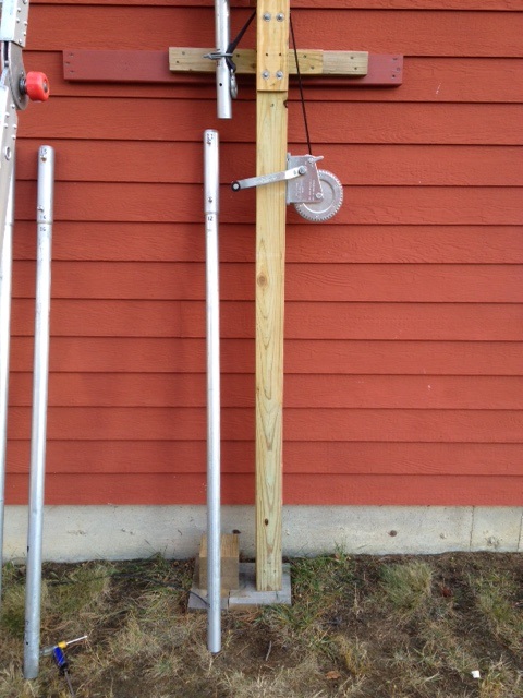
- Mounting a pair of standoff brackets on a wall or a vertical 4x4x12′ pressure treated beam with the lower standoff at 6+ feet up and the top one up about 10 feet. I used 4” standoffs rated at least for a 2-1/2″ mast. I use my Winch-It-Up Mast Support which is basically a 12′ piece of 4×4 cut at 6+ feet and 10 feet to allow for a strap winch. Click Mast Support link for details.
- Starting vertical assembly following the instructions.
- Stopping to check to be sure all pieces, including guy rings, are in the correct position and ready to go while still within safe reach from the ladder.
- Finding at least one other able bodied helper to assist. It’s much easier and more efficient than by yourself.
SPECIFIC:

Choices of Location of Mast and mounting of mast support:
1. Wall Mounted/Attached – described herein and in Mast Support link.
2. Portable or Stand-Alone – described in the Mast Support link.
You need to locate a safe place for the mast especially away from your power service.
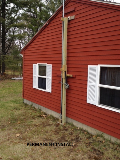
If using the Easy-Raise procedure (from horizontal to initial vertical position), you will need about 20 feet of clear area for your mast sections and antenna while still on the ground. I used a Winch-It-Up Universal Mast Support on the end of my 13′ high garage (Wall Mount) (Click MAST SUPPORT link). See Figure 1. I found at least one wall stud (two is better) and bolted a cross piece securely. I did this for an upper and lower cross piece. Check 4×4 for squareness. Add shim, if necessary. Then I attached my mast support to the wall. Every setup is different. If using the Winch-It-Up the standoff brackets must be facing left as you face the wall so your winch handle will be free to turn without hitting the wall (see Figure 12).
Determination of number of 5′ lengths of mast needed: Your desired height divided by 5. Determine quantity of couplers, reinforcers, guy rings and guy ring retainers needed to order. Figure 2 shows Coupler, Reinforcer, Guy Ring Retainer (GRR) and a Guy Ring.
COUPLERS: Every 5′ joint needs a Coupler.
REINFORCERS: They are placed at the mid-point of 5′ pieces for extra strength and rigidity. They are only used on mast sections above your top standoff bracket. They do not replace the need for proper guying.

GUY RING RETAINER (GRR): one at the top guy level is needed. As otherwise needed, the Couplers and Reinforcers act as the lower level Guy Ring Retainers so only one GRR is needed.
GUY RINGS: This system is designed for guy rings of Max-Gain Systems, and using only guy rope. Do not use with any abrasive material or metal. Generally, one ring for each 10′ of mast unless otherwise supported. They can be ordered from us with our other items – no additional shipping charge.
Cut mast material into 5 footers as you determined you needed. The straighter the cut, the better. A metal cutting saw is much less effort than a hacksaw. If using a power cutting saw, observe all safety practices and wear goggles. After cutting pieces, file the rough edges or the Couplers won’t fit properly. NOTE: Do not use an abrasive saw as the heat will distort the ends.
Preparation of sections, drilling 5/16″ holes and numbering the pieces:
Having determined how many 5′ sections you will need and having cut them, lay them out on the ground in order from the top section to the bottom section. Starting at the top, place your couplers and guy ring retainer where they will be placed along the mast. This is a good time to mark the couplers starting from 1 to 14 or thereabouts (see Figure 3). Starting at the top, mark the top most coupler’s top half and the bottom of the top 5′ section with the number ‘1’ (I used an ink marker). The bottom half of this coupler goes into the next 5′ section of the mast pipe. Mark the number ‘2’ on these pieces. Continue on down the mast until all couplers and 5′ mast sections have corresponding numbers. Now, having marked all couplers and 5 footers with matching numbers, you are ready for the drilling process knowing the pieces will be matched correctly during the drilling process and the mast raising.
Note: when drilling holes, drill bits will last longer if they are lubricated with oil during the process. A cheap brush and leftover motor oil works for me.
Preparation for joining sections together:
COUPLERS and mast pipe drilling.

Find a convenient and flat location to work on the pieces. Slide the coupler with the number ‘1’ on it halfway onto the end (about 4”) of the mast piece with the number ‘1’ on it and ink mark the spot for the hole-to-be. Center punch the spot (keeps the drill bit from wandering when drilling). Slide coupler off and using a drill press or regular hand drill, drill a 5/16” hole, one wall only, in the mast piece. Start with the smaller drill bit to better establish the desired hole location. Clean and file off the burr. Slide coupler back on and line up holes. Screw a 5/16-18 x 1” pan head bolt through both pieces. Note: be sure to slide coupler off when drilling 5/16” holes so not to damage the coupler’s threads.
With the bolt still in place, slide the next piece of mast, with the number ‘2’ on it, into the open end of the coupler, with the number ‘2’ on it, all the way until both mast pieces touch. Mark spot for drilling as before. Remove the mast piece and drill the 5/16” hole, as before, clean and slide it back into the coupler. Check for fit using bolt. If slightly misaligned, slide the Coupler off and elongate the 5/16″ hole a little with a small round file (like a chain saw file). Check for fit.
At this time you can drill the hole for each Reinforcer you will use as you get to them. Measure in 2-1/2′ on each 5 footer and mark and drill a 5/16” hole. Clean and deburr. Remember, you only use Reinforcers on 5′ sections above the top standoff. Continue this process until you finish drilling and fitting your last piece of mast. You can separate the couplers from the mast after fitting, as necessary, for convenience during the drilling process.
During the raising process, you will be adding 5′ sections to the bottom of the mast. These 5 footers should have the appropriately numbered Coupler already attached at the top and bolted in to make the raising easier. See Figure 4. You can also attach the Reinforcers at this time.
GUY RING RETAINER (GRR):

For Wire Antenna Installs: If you are erecting this mast for use as a center/balun support for a wire antenna, you will probably install your top Guy Ring Retainer a foot or so under the very top of the mast, so the guys won’t interfere with a balun or other centerpiece.
For Rotator at Top of Mast: However, if you are placing a rotator at the top of the mast with a beam, consider the following thought. The area directly under the rotator is going to be the weakest link on most masts, generally, because there is no guy support above this spot. Thus, the wind loading bending effect will be maximized here. To virtually eliminate any unsupported pipe exposure here, mount your GRR with an inch of clearance below the lower rotator clamp. This leaves enough clearance for the guy ring to move freely with the guy ropes installed. (See Figure 5). So with negligible clearance allowed around the guy ring, it will be much more difficult for the pipe to bend here.
For Rotator at the Base of the Mast: With the antenna and mast both turning, the area just under the antenna is where you will probably need more space for the coax 450 rotation loop. If so, install the GRR down about 10” +/- from the antenna base (see Figures 5a and 5b). If using EMT for the mast, I suggest you place a Coupler in this space so you don’t compromise the mast’s rigidity. If using 1.9” Fence Rail of at least 0.090” wall thickness, you probably don’t need to reinforce this space. Don’t forget to drill a hole in the mast to accommodate the pan head bolt. The 2nd hole in the coupler is not used in this operation. NOTE: I allowed 6′ +/- of coax for my loop in the 10” space and did reinforce the EMT with a coupler. For the closest fixed (non-moving) part, which is the guy ring, I attached the lower end of the coax loop with a clamp. I used the 5th hole in the guy ring with a narrow worm clamp and some electrical tape to keep from chafing the coax.


Back to the GRR…mark the hole location on the mast pipe and center punch the spot. Slide the Retainer out of the way and drill the 5/16” hole-one wall only. Slide Retainer into place and fit with a 5/16” pan head. Also, make any other necessary holes on this section at this time while it’s still convenient.
VERTICAL INSTALLATION (not using the Easy-Raise procedure). Finally – Raising the mast/putting the pieces together.

If mounting to a building side or end (as I have) with a Winch-It-Up Mast Support or equivalent, have a ladder on the wall. On the ground join the 5′ section with the number ‘1’ on it with the 5′ section having the Coupler 1,2 attached to it and insert and tighten the 5/16 x 1” pan head. You now have 10 feet of mast together with Reinforcers. Make sure you have the top guy ring installed and sitting on the Guy Ring Retainer and have drilled any other holes needed for your type of antenna. Also, slide a guy ring up from the bottom a foot or so of this now 10 footer and temporarily tape it there. This guy ring will eventually rest on the coupler of the next 5 footer you are about to install. If the top 5 footer is going to have an open top, you should cap, tape or otherwise seal it to keep the elements out. Stand this now 10 footer upright in your lower standoff bracket with the front strap loosely holding it. Now, manually, push the 10 footer high enough to clear the top standoff. You can do this by adding the next 5 footer (having Coupler 3,4 on it) or just temporarily placing a short piece of 4×4 or other block upright at the base to support the mast. The purpose of this step is to allow the guy ring to clear the top standoff so you can connect your guy ropes to it and perform other tasks (attaching coax, control cables, etc.) while that guy ring is still handy to reach. You can now, if not already done, loosely attach the top standoff’s front strap.
VERTICAL INSTALLATION (using the Easy-Raise procedure)
It’s basically the same procedure as above except you will be assembling the 5′ sections while on the ground. If you are placing a beam/rotator on top, you may want to consider using my SWIVEL BASE and the Easy-Raise Procedure shown in Figure 6 and described more completely in the ‘telescopic’ link and generally below.
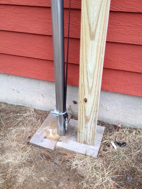
Step 1: Place your Multi-Purpose Ladder (MPL) in line with the swivel base and at a distance so that the mast will be hanging over the ladder top a convenient amount. Please your mast’s base inside the swivel cylinder (ensures no movement of mast when raising) and extend the mast over the MPL ladder. You should have 15 feet of mast assembled. I had a multi-purpose ladder standing about 7-8 feet high. This accommodated my hex being easily attached to the mast by two people (easier than by oneself). With a smaller antenna adjust the ladder height to suit your needs. Attach your antenna now and your top level guys, if not yet attached. See Figure 7.


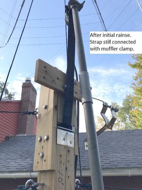
Step 2: Attaching strap winch to mast. Extend your winch’s strap out enough so that you can place it through the 1″ opening at the 10 foot level and down the mast side until it is extended along the mast until it reaches the Reinforcer located at the 12-1/2′ point of the 15 foot length. Attach it to the Reinforcer with a muffler clamp.
Step 3: Check antenna, connection, swivel, and that the winch strap is tied tightly with a muffler clamp (1 clamp directly on the Reinforcer). See Figure 8.
Step 4: Cranking it up. With the strap tight, start the cranking process. Don’t rush it. It will go up quite easily. When vertical the strap will be taut so the mast isn’t going anywhere. Now you can push the mast into the standoff by hand. While holding the mast, hand tighten the lower standoff. Then, from the MPL, loosely connect the top standoff, then unhook the winch strap from the Reinforcer.
For more info on the Easy-Raise procedure and the base Swivel, click on the Telescopic link.
Note: After the initial Easy-Raise is complete, you need to safely reach this 12-1/2 foot mark safely from your MPL to remove the clamp. So, your MPL will have to be capable of extending to at least 16′. This means there will be 8 or more steps when in the MPL position. Safety instructions state you need to have two unused steps for safe use. So, you need 6 usable steps. This is based on my estimates for a man’s average height (5′-9″) and subsequent arm’s reach. See Figures 9 & 10. Note: This ladder requirement applies only to the Stand-Alone/Portable options.

After the initial raise, you will probably want to remove the strap from the 10′ level back to the 1″ opening at the 6+ foot opening.
Note on guy ropes: make sure you have your guy ropes cut to the appropriate length needed. I use the Pythagorean Theorem to figure my lengths and added several more feet. Attach them as you proceed, but do so before the guy ring is out of your safe reach.
Note on cabling: I used zip ties and electrical tape every few feet on the mast to secure them.
ATTACHING WINCH STRAP TO MAST PIPE (only if using the Winch-It-Up)
Caution on winch hookup to mast (Figure 11): Lower the strap to the bottom of the lower mast section. When attaching the winch strap to the mast pipe, I used a 2” muffler clamp. Clamp it in the web area just above the winch’s hook to a spot about 6” up from the bottom of the 5′ section you are adding. You can see the 2” clamp attached about 6” up from the bottom of the mast piece. Don’t over tighten the clamp and don’t place it in the zone where the next Coupler will be placed as the muffler clamp may ding the pipe and then the Coupler won’t slide on to the pipe. Also: when winching up, try to keep the winch strap in the center of the 1” opening. If it rides to an edge, check if the winch is level and make a slight adjustment to the winch’s base lag bolt (play in the winch’s bottom mounting groove) or manually readjust as you proceed.
BACK TO ADDING ADDITIONAL 5′ SECTIONS (when using the winch)
Now raise the winch to a point where the next 5′ pipe section (with coupler already attached) can clear the bottom of the installed mast. See Figure 12. Place the top of this next 5′ section into the mast bottom, line up the hole and insert and tighten the 5/16 x 1” pan head bolt. Note: if there’s not enough clearance to install that 5′ section, simply remove the lower pan head and let the coupler slide down on the pipe for an extra 4” clearance. Then slide the coupler back up into position and install and tighten both pan heads.
Now you need to reverse the winch’s direction and lower the mast until it touches the ground to take the weight off the winch. Put a board under the pipe to keep it clean. Now with no weight on the winch, loosen the winch strap and remove the 2” clamp and lower the winch strap back to the ground area and install the clamp at the mast’s bottom up about 6” as you did on the previous section. Reverse the direction and continue raising the mast another 5 feet.
At this point you need to be tending your guy ropes and watching for any natural leaning. Also note that you need a guy ring every 10′ of mast so at every other 5′ addition, you need to slide a guy ring on the pipe. Tape it to the mast pipe, if need be, to hold it until the next coupler is attached below it.
PASSING GUY RINGS THROUGH STANDOFF BRACKETS (Wall Mounts)
When using the Winch-It-Up Mast Support or a straight 10′ piece of 4×4, you will probably use a 4″ set of standoff brackets. These are available from many online sellers.
Make sure your purchase can accommodate a 2-1/2” diameter mast and my advice is to stay away from the U-bolt type as they are more difficult to work with in our setup. When passing the guy rings through these brackets, it is necessary to have as much free play as possible. Even then it will be necessary to remove the strap to pass the guy ring.
Before removing the front strap, tighten-up the installed rope guys to not-quite-tight; leave a little play in them. This way you can remove the top bracket’s strap and pull the mast out enough to pass the guy ring while not worrying about the antenna/rotator (or other antenna) from leaning the mast out of control. After passing, replace the front strap to its former loose adjustment.
If you have difficulty passing the guy ring through the lower standoff bracket for lack of enough free play, raise the mast off the ground with the winch. This will give you a bit more movement in the mast. If not using a winch, you will need an extra person to hold the mast off the ground.
CAUTION: As with other standoffs, they are not designed to support the weight of the mast when it is off the ground. They simply hold the mast in place to a vertical support or a wall. The strap winch in the Winch-It-Up mast support acts as the support for the mast and can be operated by oneself.
BACK TO ADDING 5′ SECTIONS
You now have 20′ of mast up with a guy ring at the top, one down 10′ and another down another 10′ (if using three guy levels). You should have the ropes attached to the top guy ring by now. Continue adding 5′ sections until all are used up. If at 30′ or higher and with a 20-30 # load on top, I recommend that you use the 4 guy system.
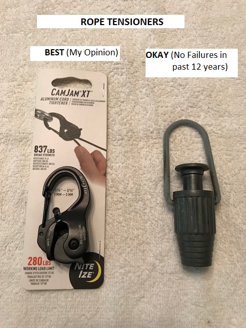
When you have reached you desired height, you need to secure the standoff brackets and tighten the guy ropes. I use Cam-Jam XT tensioners and the equivalent to the Buckmaster Line-Grip™. The XTs are much higher rated, but I have never had a Line-Grip™ type failure in 12 years of use. Note: they are also called Clothes Line Tighteners. See Figure 15.
Figure 13 shows a portable install. Mast is at 40′ high with K4KIO hex on top with rotator. Figure 14 shows a permanent install at home. It’s at 50+ feet with K4KIO hex and rotator on top.


Read all the safety and installation information you can find on other web sites on proximity to power lines, guying, wall mounts, mast raising and grounding-don’t take any chances. Become an expert – not a victim.
Having secured the standoff brackets and your guys, hook up cables and grounds and take it for a test!!!
NOTE: Advantages from using the ‘Winch-It-Up’ Antenna Mast Support
- You can work by yourself, if necessary.
- If raising a small beam, say 20-30 #, the leverage makes it seem lighter and easier to raise.
- It can eliminate the need for another person to add 5′ sections while you hold the mast up.
- You can stop anytime in the raising/lowering process because the winch can lock in place. So you can make adjustments, ie, adjust guy ropes, release a hangup at the standoffs.
- Using the 1″ opening at the 10 foot level, you can easily raise your mast/antenna and rotator to vertical by yourself, if necessary. See Figure 6.