DIY ‘WINCH-IT-UP’ ANTENNA MAST SUPPORT
USES & CONSTRUCTION PROCEDURES for BUILDING the IMPROVED and more VERSATILE DIY ‘WINCH-IT-UP’ MAST SUPPORT
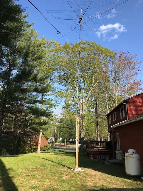
Goal of this DIY project: Construct a rugged 4×4 pressure treated DIY Winch-It-Up MAST SUPPORT that is suitable for permanent wall mount, stand alone or portable use. It’s designed for use with 5′ sections of mast and telescopic masts with an 8′ top section, like the Rohn 9H50 type.
General Info:
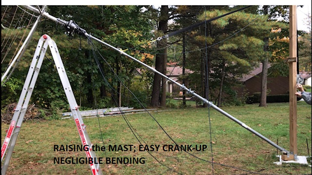
The mast support includes a strap type winch to assist in the mast raising, to hold it in place, and to support its’ weight while adding sections of mast you will use. Also, just added, is a feature that allows you an easy, from the ground, crank-up of the mast to its’ initial vertical position even with antenna/rotator mounted on top. This crank-up can be easily done by one person. See Figures 1, 2.

Each mast has two 4″ Standoff Brackets, a strap winch, two 1 inch openings to accommodate the winch’s strap/clamp and some other small pieces. You will also need up to 8 feet of a 1×4″ pressure treated (PT) board.
Important Note: The two 4″ Standoff Brackets need to be rated for at least a 2-1/2″ mast size and purchase the type with the removable front strap. See figure 3.
The strap winch can be locally procured and comes standard with a 20 foot strap. With an 8′ top section, the 20′ standard strap will work just fine.

The support can be configured in different ways to meet your needs.
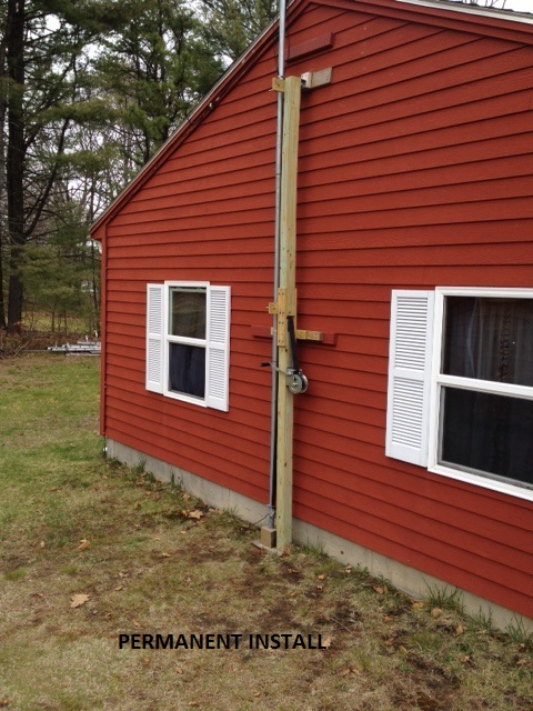
Option 1. Wall Mounted/Attached. See Figures 4, 5.
Option 2. The Stand Alone/Portable. This option will require having three (or 4) guy ropes near the top of the 4x4x10′ for stability.
OPTION 1: Wall Mount/Attached
This method mounts your mast directly to a wall. Look for at least one stud to connect to your mounting mechanism. See Figures 4 & 5.
Step 1. For this option cut a 6-1/2′ piece and a 3-1/2′ piece, and two 8″ pieces. You will also need two 12″ pieces and four 15″ pieces of 1×4″ pressure treated board. Two 12″ pieces will hold the standoff brackets and two 15″ pieces will join the lower 6-1/2 footer to the upper 3-1/2 footer. The other two 15″ pieces will hold the top 8″ section to be added to the main 4x4x10′ section. You will also need some sheet metal scraps to overlap the 1″ openings, about 24 inches of it. See Figures 6, 7 …for construction layout.

Step 2. Lay the 6-1/2′ and 3-1/2′ sections on the floor with a 1″ separation between. Place a 15″ piece equally across them. Square the 4x4s as best you can. Drill three holes in a triangular pattern at each end and attach with 5/16 x 1-3/4″ lags. Now flip the 4x4s over and attach a 15″ piece as before. See Figure 7.
Step 3. Now take your 12″ sheet metal piece and equally spread it over the top of the 6-1/2′
4×4. Attach on one side with roofing nails, then pull it tight over the top to the other side and attach. Make sure the sheet metal spans the Total Width of the 4×4 top. I had to overlap two pieces of sheet metal to cover the total width. Make sure the sheet metal fully covers the opening including any spaces between mounting boards even running it a bit up the sides. This, along with a level winch should keep the strap from wandering and catching on one side. This sheet metal will reduce the friction from the strap as it goes across while raising.
NOTE: This 1″ opening is not necessary if only using the support for a telescopic mast raising.
Step 4. Attach a 12″, 1×4 crosspiece to the 4×4 up about one inch over the 1″ opening centered and attach with two 5/16″ Lag Bolts. If you have the Standoffs on hand, you can drill and mount one standoff centered on this crosspiece. I use 5/16″ x 1-1/2″ bolts for this.
Step 5. Move up to the top of the 4×4. Hopefully, you have a fairly straight and not badly warped length. Attach two 1x4x15″ PT pieces vertically to the sides of the 4×4 as follows. See Figure 8 for orientation direction. Overlap 6″ onto the 3-1/2 foot 4×4 and attach with three 5/16″ lag bolts set in a triangular pattern. Repeat the process for both sides. Then attach the 2nd sheet metal strip over the 4×4 as done before.

Step 6. Take an 8″ piece of 4×4 and attach it to the two side pieces of the1x4x15s as follows. Leave a one (1) inch opening above the 3-1/2 foot 4×4′. That leaves 8″ to mate evenly with the top of the 1x4x15″ pieces. Drill and attach with three 5/16″ lag bolts in a triangular pattern. Repeat the process on the other side. The 1″ opening allows for the winch’s strap to easily pass through. See Figure 8.
Step 7. With the other 1x4x12″ cross piece, you can mount it in the center of the 8″, 4×4 piece, but do not mount the standoff to it yet. It is placed about 1/2″ above the bottom of the 4x4x8″. The standoff will be mounted later when you square your mast vertically.
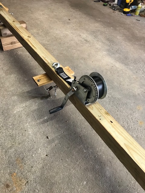
Step 8. Mounting the Strap winch. Mine has three mounting holes on it. I used 5/16x 1-1/2″ lag bolts for this. I mounted mine up about 5-1/2′ from the ground. Try to align the two top holes on a level straight line to help keep the winch mounted as level as possible. See Figure 9 for its’ orientation on the 4×4. It mounts on the backside of the standoff brackets. Because the antenna, rotator and mast itself have substantial vertical dead weight, it may be difficult for some to easily crank the winch. What I did was add a length of steel bar that I found to the crank handle to give me the necessary leverage. I set it up so I could use both hands to turn the crank-works very nicely. Be careful to avoid the extension from hitting the lower standoff backing board. See Figure 10.
Note: When mounting, if the lower mount hole is directly under the coiled strap, unwind the strap for easy access to the lower mounting hole


OPTION 2: PORTABLE or THE STAND ALONE
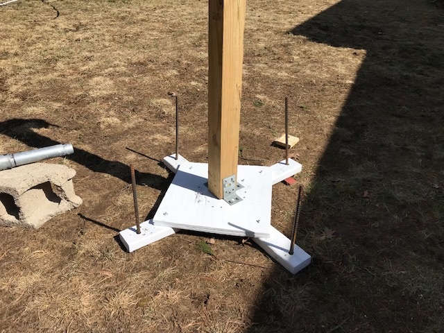
The Portable method uses the same 10′ main 4×4 as in the ‘attached to a wall’ option. The mounting parts to the 4x4x10′ piece are the same for the ‘Portable’ as the ‘Attached to a Wall’ version except you add a base to the Portable. In this case you need to construct a base and attach the Mast Support to it. Three guy ropes at the top are also required for this option. For my portable base, see Figure 11, I used 2 pieces of 1/2″ plywood (on hand) about 18×18″ square that were placed together. Also the base included a 36″ piece of 2×4 placed diagonally and two smaller 2x4s that made up the other diagonal. I drilled holes near the four ends to accommodate 24″ rebar stakes. Also, I used three 90 degree plates to attach the mast and base. The mast side doesn’t need a right angle plate. You’ll use this spot when building your swivel base. Your base design can be very different as long as the base is secured.
Using The Stand Alone method, the 4×4 PT could be placed directly in the ground in an open area. For this you need to start with a 4x4x16 foot PT and three guy ropes at the top would be necessary. A 16 footer would allow you to place it in the ground about 3-4 feet and still have the necessary minimum above ground height of 10′ plus the 8″ add-on. So the vertical parts that show are the same as the Portable system.
If you are using OPTION 2, the Stand Alone or Portable, you will need to attach three 1/4″ screw eyes near the top of the 10 foot section. Place them on the three sides not including the standoff bracket side, so, two on the sides of the main 4×4 and one higher up on the back side of the 8″ extension piece. See Figure 6 (above).
Note: If using the Stand Alone or Portable option, three guy ropes at the top is a minimum-I have 4 of them. I placed two of them on the same eye bolt. Also Important: Have one guy rope directly opposite from the direction from which the mast is raised. This will keep the mast support from leaning when the raising begins.
This completes the Mast Support section.
PART 3: ADDING a SWIVEL BASE
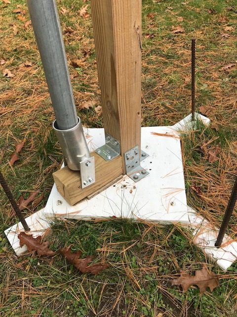
This cylindrical swivel allows you to keep your mast’s base in place while raising/lowering. It consists of a 2-7/8″ OD metal cylinder attached to a 8″ piece of 4×4 placed at the mast’s base. A right angle metal bracket connects the 8″ piece to the main 4×4. Lowe’s has a good one made by Simpson Strong-Tie, 2x2x3. It comes with 1/4″ holes. I drilled the 1/4″ holes out to 5/16″ and mounted with 5/16″ lag bolts. The Swivel Kit comes with two pre-drilled metal 2×4″ straps and all hardware. See Figure 12.
NOTE: The swivel is a handy addition to your mast raising, but is only necessary if raising your mast from the horizontal ground position to the initial vertical position using the easy crank-up step. It keeps the mast’s base from moving out of control especially if working by yourself.

Step 1. If your winch-it-up mast support is not vertically in place, set it up vertically and attach guys, anchors, rebars (if used), etc. Make sure it’s as vertical as possible.
Step 2. I attached the 8″ piece of 4×4 at the base after the mast was standing at its’ location. It mounts/lays lengthwise and is perpendicular to the main 4×4 support. I used the right angle bracket here with 1-1/4″ lag bolts. The 8″ piece can be laying directly on the ground, but you might want some scrap material under it for more protection/rigidity. You have flexibility here as long as the swivel and its’ base are secure. See Figure 13.
Step 3. Aligning the Swivel for a vertically square mast. Have a level handy in your pocket. With a couple of your mast’s sections exposed and sitting on the ground without antenna and G-450A (if used) attached, hand raise the mast vertically so you can loosely connect it to the lower standoff. While holding it against the lower standoff, with your other hand place the mast’s base on the 8″ 4×4, adjust it so it is vertically square and tighten the lower standoff. Take your magic marker and mark on the 8″ piece with a circle where the mast sits on it. Now you will be as close to vertical as is reasonably possible. The top section plays no part in this alignment if using a telescopic mast. Note: If you have a straight odd metal pipe that’s easier to use than the mast, for this operation, use it. See Figure 13.
Step 4. Placing your Swivel on its’ 8″ base. See Figure 5 (above).
Your swivel has two pre-drilled 4″x2″ straps. Attach the single hole end of the two straps to the cylinder with the provided spacers or washers equally divided between the outer cylinder walls and the straps and then tighten using the 4-1/2″ bolt and nut. Don’t mix up the 4×2 straps. They’re marked A and B. Keep them in the same position all the time as they may not be exact copies of each other. Line up the brackets so the 2-7/8″ cylinder is centered on the circle you marked earlier. Mark and Drill two holes in the sides of the 4x4x8″ and attach with 5/16×1-1/2″ lag bolts. Make sure you have allowed an inch plus clearance from the bottom of the cylinder (when upright) to the top of the 8″ 4×4. I used a 7/32″ drill bit for 5/16″ lag bolt holes though a 3/16″ bit will work fine. Tighten the 4-1/2″ bolt so it has some resistance so you can change the cylinder’s angle as needed, but it stays in place.
Standoff Brackets:
4” standoffs of the Strap type. They need to be able to accommodate a 2-1/2” mast pipe.
The mast support structure is now complete.
GENERAL INVENTORY LISTING
- 1 ea 4 x 4 x 12′ pt(pressure treated) beam
- 1 ea 1 x 4 x 8′ pt board
- 16 or 20 ea 5/16 assorted lag screws(hex heads)
- 4 ea 5/16 x 1-1/2” hex bolts, USS
- 5/16” flat washers
- 4 ea 5/16-18 nuts (threads to match bolts)
- 3 ea ¼ x 3” screw eyes (eye lags), if needed
- 3 ea lag screws to fit winch (5/16 x1-1/2” fit mine)
- 2 ea 12” piece of 3” to 3-1/2” flashing w/8 roofing nails
-All of the above came from a local hardware and lumber store except the flashing which I had laying around.
- 1 pr 4” standoff brackets. 4” standoff brackets are commercially available.
- 1 ea strap winch 1500# came from local discounter.
Companion Mast Info:
What type of mast would work with this support? In short, most masts made with 5′ sections and less than 2-1/2” OD will work. Also: A Rohn 9H50, with an 8′ top section, telescopic mast was used with the Winch-It-Up Mast Support. In my case, I’ve used three different sized mast materials with Couplers and Reinforcers of my own design.
The antenna mast materials used with this support so far have been either 1.9” OD fence rail (sized in several wall thicknesses-I used 0.090”) available from local fence suppliers or 1-1/2” EMT (1.740” OD x 0.065” wall x 10′ long) available from home supply/electrical stores. They are cut into 5 foot sections and joined together with 8” long DOM steel Couplers. Then 5” long Reinforcers are placed mid-way on the 5 footer for extra strength and rigidity. One Guy Ring Retainer, about 1”+/- wide, is needed to hold the top Guy Ring in place. Guy Rings required for these two mast sizes are of Max-Gain Systems, Inc design. GR-175 fits the EMT and GR-2 fits the 1.9” fence rail. Guy rope is used with the guy rings-no abrasive/metal guys.
Also: The Rohn 9H50 telescopic mast uses three 5″ Reinforcers only on the top 1-1/4″ OD section and a 6″ Adapter Reinforcer, if needed. Also, one Guy Ring Retainer is used at the top. Factory guy rings were used.